|
|
|||
|
|
|||
|
|
dSL
Information
dSL is a programming language used to program industrial controllers. Industrial controllers have a processing unit, a central memory, and an interface to the environment.
With dSL, the environment can be anything from traffic lights to tunnel ventilation systems or assembly lines. Each such a controller can observe the environment through sensors,
calculate a reaction to what it sees from the environment and gives feedback through its actuators. Sensors may be of any kind : temperature, presence detection, speed, ... while actuators can
change valves, run engines, etc. Papers on dSL An overview of the distribution aspects of dSL can be found in the following paper : Results on the complexity of the distribution problem can be found in the following document: Preliminary results on the verification of dSL, using the Spin Model Checker can be found in the following paper :
An extended overview of the semantics and the properties of the semantics can be found in the following journal paper :
Technical reports and other information on dSL A very short introduction
on dSL can be found in my DEA work The complete dSL grammar can be found here In this master thesis, I assisted Nicolas Devos who made a backend to the dSL compiler in order to make it compile dSL programs with
Legos Mindstorm as target platform. |
|
|
|
dSL
Demo
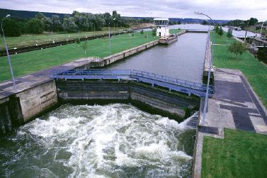
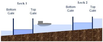
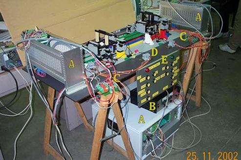
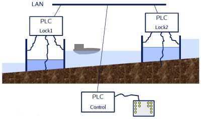
A demonstration of the dSL concept has been realised using Lego Mindstorms. We are using a model of two locks that introduces some interesting constraints.
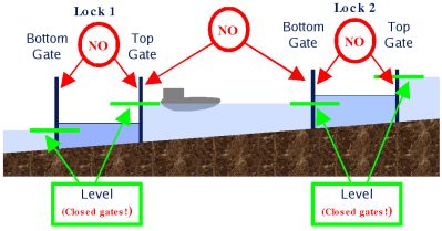
The constraints on the allowed actions for the two locks are :
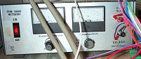
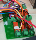
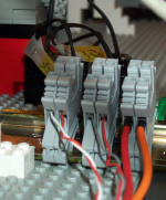
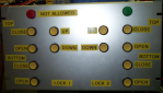
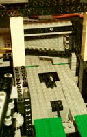
We realised the model of the two locks using Lego Mindstorms interfaced to 3 PLC (controllers) (A) from Macq Electronique. To command the lego motors, a DC source is used (B), and to inverse its polarity based on one of the outputs of the PLC, a small piece of hardware was realised (C). This was needed to command the direction of the Lego Mindstorms engines. We had to adapt the wires of the Lego Mindstorms connecters to interface to the PLCs (D). And last but not least, the control panel (E) is interfaced to one of the PLCs to issue the commands. Remark the control panel's red not allowed led that indicates actions that do not respect the above constraints. |
|
|
|
(A) |
(B) |
(C) |
(D) |
(E) |
|
|
|
The dSL source code can be found here. The intermediate code (control flow graph) is in binary form and thus not very interesting to look at. The dSL Virtual Machine code produced by the distributer can be found for PLC1, PLC2 and PLC3. Remark that the dSL program does not contain any distribution information. This information (the locations of all input/outputs) comes from the database that is integrated in Macq Electronique's OBviews.
It assigns all buttons (and the led) to PLC1, all I/Os for lock1 to PLC2 and all I/Os for lock2 to PLC3. No other information is needed.
|
|
|
|
MPEG
|
MPEG
|
MPEG
|
MPEG
|
|
|
|
None available.
|
|
|
|
The aim of verifying dSL programs is to offer the programmer a utility that enables to fully test the designed software for bugs. This is done by exploring all execution traces in a simulated environment and check that no bad states are reached.
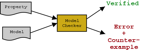
A model checker is a utility that enables automatic exploration of the global state space (the set of all states reached following all possible execution paths) while looking for violations of two kind of properties :
The Model Checker answers that the property is verified when there is no execution trace that violates the property, or gives an error trace that violates the property as a counter-example. Some preliminary results are obtained using the Spin model checker on the canal lock example cited before. The results of these experiments show a real need for the use of verification in safety-critical software design. Indeed, an error was discovered in the canal locks controller, that is caused by bad use of the synchronisation variables in the program. The error first discovered using the model checker, can be classified as improbable since it requires a specific timing on behalf of the operator to open both gates of the same lock. However, the error was actually realised on the Lego model after 10 minutes of hard effort. These kind of errors are almost impossible to detect in a common testing environment, but can jeopardize equipment and even lifes. Verification is therefore a must. Read all about it here.
|
|
|
|
More
information Please, feel free to contact me with any question you may have. Return to my home page to find out how to contact me.
|
|
|
|
|
|